MacOS M2+VScode+ESP-IDF+Atom Liteでクリックを検知しLチカさせる方法の備忘録
MacOS M2+VScode+ESP-IDF+Atom Liteでクリックを検知しAtom Liteの内蔵LEDを点灯させる方法までに調べたことやわかったことなどの備忘録まとめです。どなたかの参考になればとおもい記述しておきます。
Arduino、ESP32、M5Stackについて
Arduino、ESP32、M5Stackについて学びましょう
【初心者向け】Arduino、ESP32、M5Stack、M5StickCの違いをわかりやすく解説
人気のマイコンモジュール「M5Stack」とは?特徴や使い方を紹介!
こちらの2つのサイトがわかりやすかったです。
要点をまとめると
- ESPかAudinoどちらでビルドするかを決めなければいけない
- Atom LiteはM5Stack製
- M5StackのCPUはESP32なのでESP環境(VScode+ESP-IDF)かArduino環境(VScode+PlatformIO+Arduino-esp32)を使用する必要がある
- Arduino-esp32はESPをArduinoを動作させるもの
- ArduinoはESPをより簡単にした言語になるので、Arduino-esp32で作成するより、ESPで作成したほうが色々なことができる
- サンプルがたくさん出てくるM5AtomやFastLEDはArduinoのライブラリなのでESPでは動かない
- 結論:VScode+ESP-IDFでAtom Liteの内蔵LEDにアクセスしLチカさせクリック検知と合わせて実装する方法を探すと良い
M5Stickの内蔵LEDを使う方法
M5Stickの内蔵LEDを使うにはLEDがどのGPIOに対応しているか調べる必要がある
一般的なArduinoだとGPIO13とかにLEDがついていることが多いですが、開発ボードによって内蔵していなかったり、違うPINにつながっていたりします。
M5StickCは裏側を見ればわかるのですが、GPIO10に接続されています。また、LOWに落とすことでLEDが点灯しますので注意してください。
上記サイトによるとM5Stick製の製品には製品に貼ってあるシールや製品のサイトに対応するGPIOが記述されているらしい
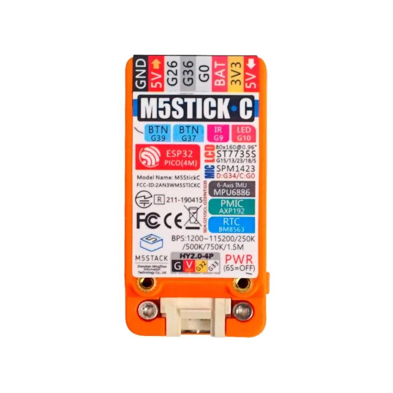
確かにM5StackCの製品紹介をみるとLEDのところがG10となっている
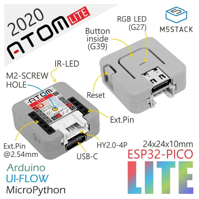
ではAtom Liteではどうなっているのか
製品紹介サイトをみるとRGB LEDはG27となっている
このためGPIOは27を指定すればいいことがわかる
VScode+EPS-IDEでLチカのサンプルコードblinkを作成して試してみる
vscode + espでLEDのサンプルblinkを作成しGPIOを27にして試してみました
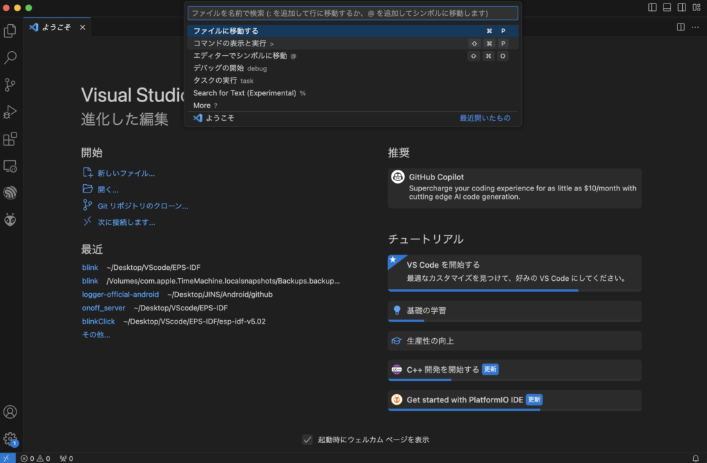
コマンドの表示と実行 >
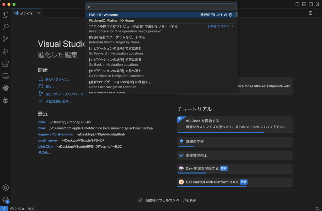
ESP-IDF Welcome
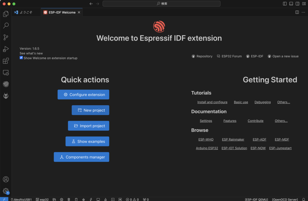
New project
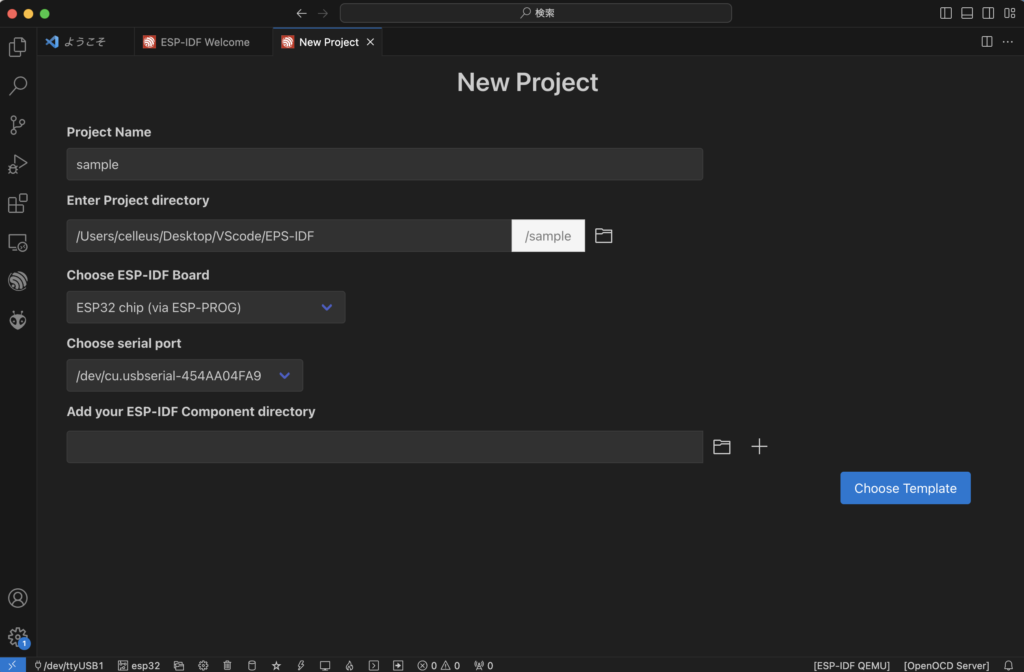
諸々を記入して
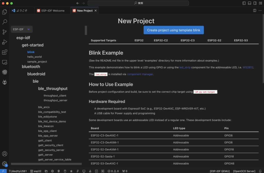
ESP-IDFのblinkのサンプルプロジェクトを新規で作成します
次に
#define BLINK_GPIO CONFIG_BLINK_GPIOこの部分を
#define BLINK_GPIO 27に変更し
#ifdef CONFIG_BLINK_LED_RMTCONFIG_BLINK_LED_RMTのほうのプログラムを使用すればokです
以下サンプルコードの全文、こちらでAtom LiteのLEDがチカチカ点灯します。
/* Blink Example

   This example code is in the Public Domain (or CC0 licensed, at your option.)

   Unless required by applicable law or agreed to in writing, this
   software is distributed on an "AS IS" BASIS, WITHOUT WARRANTIES OR
   CONDITIONS OF ANY KIND, either express or implied.
*/
#include <stdio.h>
#include "freertos/FreeRTOS.h"
#include "freertos/task.h"
#include "driver/gpio.h"
#include "esp_log.h"
#include "led_strip.h"
#include "sdkconfig.h"

static const char *TAG = "example";

/* Use project configuration menu (idf.py menuconfig) to choose the GPIO to blink,
   or you can edit the following line and set a number here.
*/
#define BLINK_GPIO 27

static uint8_t s_led_state = 0;

static led_strip_handle_t led_strip;

static void blink_led(void)
{
    /* If the addressable LED is enabled */
    if (s_led_state) {
        /* Set the LED pixel using RGB from 0 (0%) to 255 (100%) for each color */
        led_strip_set_pixel(led_strip, 0, 16, 16, 16);
        /* Refresh the strip to send data */
        led_strip_refresh(led_strip);
    } else {
        /* Set all LED off to clear all pixels */
        led_strip_clear(led_strip);
    }
}

static void configure_led(void)
{
    ESP_LOGI(TAG, "Example configured to blink addressable LED!");
    /* LED strip initialization with the GPIO and pixels number*/
    led_strip_config_t strip_config = {
        .strip_gpio_num = BLINK_GPIO,
        .max_leds = 1, // at least one LED on board
    };
    led_strip_rmt_config_t rmt_config = {
        .resolution_hz = 10 * 1000 * 1000, // 10MHz
    };
    ESP_ERROR_CHECK(led_strip_new_rmt_device(&strip_config, &rmt_config, &led_strip));
    /* Set all LED off to clear all pixels */
    led_strip_clear(led_strip);
}

void app_main(void)
{

    /* Configure the peripheral according to the LED type */
    configure_led();

    while (1) {
        ESP_LOGI(TAG, "Turning the LED %s!", s_led_state == true ? "ON" : "OFF");
        blink_led();
        /* Toggle the LED state */
        s_led_state = !s_led_state;
        vTaskDelay(CONFIG_BLINK_PERIOD / portTICK_PERIOD_MS);
    }
}
ボタンの検知と合わせる
まずAtom LiteのボタンのGPIOを調べました
GPIOは39でした
次にボタンの検知について調べました
https://docs.espressif.com/projects/esp-idf/en/latest/esp32/api-reference/peripherals/gpio.html
公式リファレンスを参考に以下のようにプログラムを修正しボタンの検知とLチカを組み合わせました
/* Blink Example

   This example code is in the Public Domain (or CC0 licensed, at your option.)

   Unless required by applicable law or agreed to in writing, this
   software is distributed on an "AS IS" BASIS, WITHOUT WARRANTIES OR
   CONDITIONS OF ANY KIND, either express or implied.
*/
#include <stdio.h>
#include "freertos/FreeRTOS.h"
#include "freertos/task.h"
#include "driver/gpio.h"
#include "esp_log.h"
#include "led_strip.h"
#include "sdkconfig.h"

static const char *TAG = "example";

/* Use project configuration menu (idf.py menuconfig) to choose the GPIO to blink,
   or you can edit the following line and set a number here.
*/
#define BLINK_GPIO 27
#define BUTTON_GPIO 39

//GPIO FUNCTIONS
#define INPUT             0x01
#define OUTPUT            0x03
#define PULLUP            0x04
#define INPUT_PULLUP      0x05
#define PULLDOWN          0x08
#define INPUT_PULLDOWN    0x09
#define OPEN_DRAIN        0x10
#define OUTPUT_OPEN_DRAIN 0x13
#define ANALOG            0xC0
//Interrupt Modes
#define DISABLED  0x00
#define RISING    0x01
#define FALLING   0x02
#define CHANGE    0x03
#define ONLOW     0x04
#define ONHIGH    0x05
#define ONLOW_WE  0x0C
#define ONHIGH_WE 0x0D

static uint8_t s_led_state = 0;

static led_strip_handle_t led_strip;

static uint8_t s_button_state = 0;

static void blink_led(void)
{
    /* If the addressable LED is enabled */
    if (s_led_state) {
        /* Set the LED pixel using RGB from 0 (0%) to 255 (100%) for each color */
        led_strip_set_pixel(led_strip, 0, 16, 16, 16);
        /* Refresh the strip to send data */
        led_strip_refresh(led_strip);
    } else {
        /* Set all LED off to clear all pixels */
        led_strip_clear(led_strip);
    }
}

static void configure_led(void)
{
    ESP_LOGI(TAG, "Example configured to blink addressable LED!");
    /* LED strip initialization with the GPIO and pixels number*/
    led_strip_config_t strip_config = {
        .strip_gpio_num = BLINK_GPIO,
        .max_leds = 1, // at least one LED on board
    };
    led_strip_rmt_config_t rmt_config = {
        .resolution_hz = 10 * 1000 * 1000, // 10MHz
    };
    ESP_ERROR_CHECK(led_strip_new_rmt_device(&strip_config, &rmt_config, &led_strip));
    /* Set all LED off to clear all pixels */
    led_strip_clear(led_strip);
}

static void configure_button(void)
{
    gpio_config_t conf = {
        .pin_bit_mask = (1ULL<<BUTTON_GPIO),         /*!< GPIO pin: set with bit mask, each bit maps to a GPIO */
        .mode = GPIO_MODE_DISABLE,                   /*!< GPIO mode: set input/output mode                     */
        .pull_up_en = GPIO_PULLUP_DISABLE,           /*!< GPIO pull-up                                         */
        .pull_down_en = GPIO_PULLDOWN_DISABLE,       /*!< GPIO pull-down                                       */
        .intr_type = DISABLED,                       /*!< GPIO interrupt type - previously set                 */
        .mode = INPUT
    };

    if(gpio_config(&conf) != ESP_OK)
    {
        ESP_LOGI(TAG, "GPIO config failed");
        return;
    }
}

static void pushed_button(void)
{
    if (s_button_state == 0) {
        s_button_state = 1;
        s_led_state = !s_led_state;
        blink_led();
    }
}

void app_main(void)
{

    /* Configure the peripheral according to the LED type */
    configure_led();
    /* ボタンの設定 */
    configure_button();

    while (1) {

        if (gpio_get_level(BUTTON_GPIO)) {
            ESP_LOGI(TAG, "OFF");
            s_button_state = 0;
        }
        else {
            ESP_LOGI(TAG, "ON");
            pushed_button();
        }


        vTaskDelay(100 / portTICK_PERIOD_MS);
    }
}
ボタンの検知には割り込み?など色々な設定があるようなのですがとりあえず上のように設定したらうまく動きました。